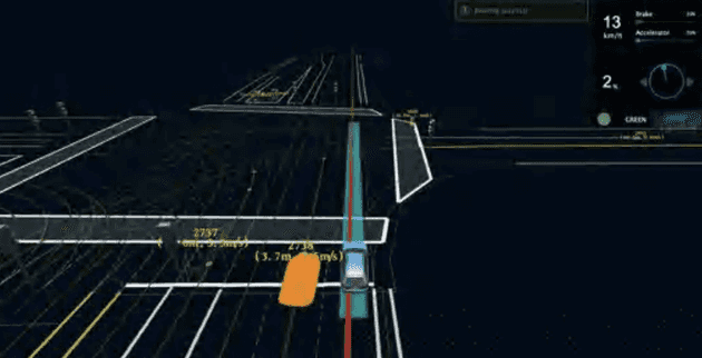
智驾场景地图上最重要的元素是啥?当属 Line 元素了,比如下图的车道线、规划线和预测线等(下图来自百度 apollo 公开课件,有点糊凑合看吧)
一些调整
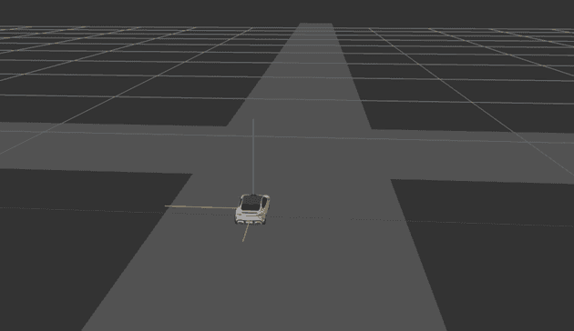
先把相机位置调一下,因为在我们认知习惯里 z 轴应该垂直向上,水平面则是 x/y 轴,这个时候在不翻转场景的情况下,可以调整相机的 up属性,使其向上位置朝着 z 轴正向,这样一来给我们造成的视觉效果就是 z 轴垂直向上
但实际上还是符合右手定则,此时的 x 轴、y 轴和 z 轴如下图所示(蓝色向上是 z 轴正方向,红色向左是 x 轴正方向,绿色向屏幕内是 y 轴正方向)。部分修改代码如下:
carema.up.set(0, 0, 1);
// 注意调下相机位置确保看到自车
camera.position.set(-0.4, 4, 1.4);
内置 Line
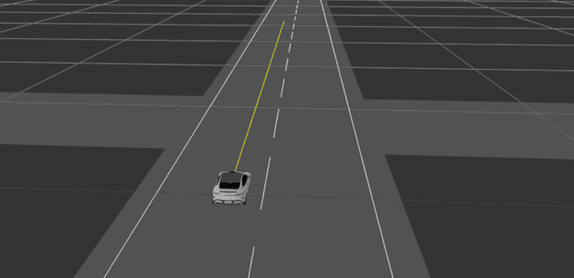
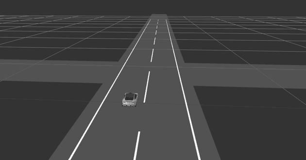
其实 threejs 也有内置的线条几何体,比如我们可以用 Line 实现几段基础的道路线,并在自车前方加一条简单的规划线
// ...
const points = [];
points.push(new THREE.Vector3(0.4, -20, 0));
points.push(new THREE.Vector3(0.4, 20, 0));
const geometry = new THREE.BufferGeometry().setFromPoints(points);
const material = new THREE.LineBasicMaterial({ color: 0xffffff });
const line = new THREE.Line(geometry, material);
line.position.z = 0.1;
this.scene.add(line);
const points2 = [];
points2.push(new THREE.Vector3(-0.8, -20, 0));
points2.push(new THREE.Vector3(-0.8, 20, 0));
const geometry2 = new THREE.BufferGeometry().setFromPoints(points2);
const material2 = new THREE.LineBasicMaterial({ color: 0xffffff });
const line2 = new THREE.Line(geometry2, material2);
line2.position.z = 0.1;
this.scene.add(line2);
const points3 = [];
points3.push(new THREE.Vector3(-0.2, -20, 0));
points3.push(new THREE.Vector3(-0.2, 20, 0));
const geometry3 = new THREE.BufferGeometry().setFromPoints(points3);
// 虚线材质
const material3 = new THREE.LineDashedMaterial({
  color: 0xffffff,
  dashSize: 1, // 显示线段的大小,默认为3
  gapSize: 0.5, // 间隙的大小,默认为1
});
const line3 = new THREE.Line(geometry3, material3);
line3.position.z = 0.1;
// 注意虚线必须调用这个函数
line3.computeLineDistances();
this.scene.add(line3);
// 自车规划线
const points4 = [];
points4.push(new THREE.Vector3(0, -10, 0));
points4.push(new THREE.Vector3(0, 0, 0));
const geometry4 = new THREE.BufferGeometry().setFromPoints(points4);
const material4 = new THREE.LineBasicMaterial({ color: 0xffff00 });
const line4 = new THREE.Line(geometry4, material4);
line4.position.z = 0.1;
this.scene.add(line4);
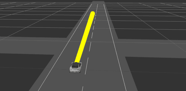
但这里发现规划线太细了,想要定义宽度 LineWidth 却发现没有效果,这里改用 Line2试试:
import { Line2 } from "three/examples/jsm/lines/Line2.js";
import { LineGeometry, LineMaterial } from "three/examples/jsm/Addons.js";
// ...
// 规划线
const geometry4 = new LineGeometry();
geometry4.setPositions([0, -10, 0, 0, 0, 0]);
const material4 = new LineMaterial({
  resolution: new THREE.Vector2(window.innerWidth, window.innerHeight),
  color: 0xffff00,
  linewidth: 20,
});
const line4 = new Line2(geometry4, material4);
line4.position.z = 0.1;
this.scene.add(line4);
先看下效果:
看起来会有点像圆柱体,而且不随视角远近而改变大小,但其实我们期望的效果只需要车道保持平行的二维固定长度的线。车道线主要是实线和虚线以及多种颜色的组合,乍一看内置元素都还能勉强实现这些,其他内置线元素还有:
LineSegments与THREE.Line类似,但是可以通过一系列的点创建出多段线,可以调节线条宽度粗细,这个在 第二篇 一开始实现立方体的时候有用来绘制边框LineLoop首尾相连的线 ,可以形成一个闭合的图形,但也没法设置宽度粗细CatmullRomCurve3创建平滑的三维曲线
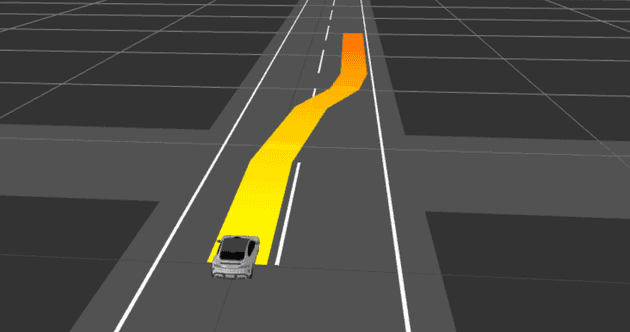
但后面突然算法找到你,说我们希望做条规划线,而且是渐变色的,渐变范围在某些点之间,可以用来表示速度变化趋势,那这个时候,内置的线元素就难办了。ok 总结一下,内置线元素有什么缺点:
- 宽度定义比较难受
- 实现虚线或者双线效果时处理数据会额外占用较多的 CPU 资源
- 不支持渐变色、流光效果等
自定义 Line
我们其实可以自定义 Line 元素和 shader 材质来解决上面的这些限制,需要用到之前的 BufferGeometry 自定义几何体和 shaderMaterial。这里得稍微了解下 webgl 的渲染管线(图片来自 threejs 中文网):
shaderMaterial
上图可以看到,先后经历了顶点着色器(vertex shaders)和片元着色器(fragment shaders),shader 代码用 GLSL 语言编写,是在 GPU 中执行的,其实有时候我们可以把一部分 CPU 的工作交给 GPU 来提升应用的性能
GLSL 入门可以参考 https://github.com/wshxbqq/GLSL-Card
这里有些属性要了解一下:
uniforms传递给 shader 的参数,比如颜色值、透明度等vertexShader在顶点着色器中运行的代码片段fragmentShader在片元着色器中运行的代码片段
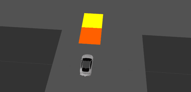
先画个双色的长方形看看:
// ...
const geometry = new THREE.PlaneGeometry(0.4, 1);
const shader = new THREE.ShaderMaterial({
  uniforms: {
    uColor: {
      value: new THREE.Color("#ffff00"),
    },
    uColor1: {
      value: new THREE.Color("orange"),
    },
  },
  vertexShader: `
    varying vec3 vPosition;
    void main() {
      vPosition = position;
      // 计算顶点的位置,投影矩阵*模型视图矩阵*模型顶点坐标
      gl_Position = projectionMatrix * modelViewMatrix * vec4(position, 1.0);
    }`,
  fragmentShader: `
    uniform vec3 uColor;
    uniform vec3 uColor1;
    varying vec3 vPosition;
    void main() {
      gl_FragColor = vPosition.y < 0.0 ? vec4(uColor, 1.0) : vec4(uColor1, 1.0);
    }`,
});
const plane = new THREE.Mesh(geometry, shader);
plane.position.y = -1;
plane.position.z = 0.1;
this.scene.add(plane);
实线
我们可以将线元素Line看成是一些三角形连接而成,然后宽度就是每个点往两边分别延伸一半,类似下图:
这里我们就需要先用 BufferGeometry 自定义 Line 元素,再把相关参数传入 shaderMaterial
先分别实现下基础的实线和虚线,老规矩先定下元素接口:
export interface ILine {
  points: number[]; // 点集,[x,y,z]
  color: string; // 颜色值
  width: number; // 线宽
  type: ELineType; // 线类型
}
export enum ELineType {
  Solid = 0, // 实线
  Dash = 1, // 虚线
  Gradual = 10, // 渐变线
  // 还可以扩展到双线、虚实线结合等
}
封装 Line,这里用到了 polyline-normals这个库,我们需要借助它来计算顶点的法向量,通过这个法向量和宽度来计算得到两边的顶点。但是这个库还没支持 ESModule,需要 require 引入,需要多安装一个 vite-plugin-commonjs插件来支持,同时修改vite.config.js 如下:
// pnpm i polyline-normals
// pnpm i -D vite-plugin-commonjs
// vite.config.js
import commonjs from "vite-plugin-commonjs";
// ...
export default defineConfig({
  plugins: [react(), commonjs()],
  // ...
});
接下来封装一下自定义的 Line 元素,BufferGeometry 自定义几何体在上一篇有比较多的内容,可以自行参考:
// src/renderer/line.ts
// ...
const getNormals = require("polyline-normals");

class Line {
  scene = new THREE.Scene();

  constructor(scene: THREE.Scene) {
    this.scene = scene;
  }

  createGeometry(data: ILine, needDistance: boolean = false) {
    const { points } = data;
    const vertices: number[][] = [];
    const indices: number[] = [];
    const lineNormal: number[][] = [];
    const lineMiter: number[][] = [];
    const lineDistance: number[][] = [];
    const lineAllDistance: number[][] = [];
    const geometry = new THREE.BufferGeometry();
    // 计算各个点的法向量
    const normalsByPolyline = getNormals(points);
    let indicesIdx = 0;
    let index = 0;
    let distance = 0;
    points.forEach((point, i, list) => {
      const idx = index;
      if (i !== points.length - 1) {
        // 添加索引以形成两个三角形
        indices[indicesIdx++] = idx + 0;
        indices[indicesIdx++] = idx + 1;
        indices[indicesIdx++] = idx + 2;
        indices[indicesIdx++] = idx + 2;
        indices[indicesIdx++] = idx + 1;
        indices[indicesIdx++] = idx + 3;
      }
      // 这里不用先计算,后面直接在shader里面借助GPU计算就行
      vertices.push(point);
      vertices.push(point);
    });
    normalsByPolyline.forEach((item: any) => {
      const norm = item[0];
      const miter = item[1];
      lineNormal.push([norm[0], norm[1]], [norm[0], norm[1]]);
      lineMiter.push([-miter], [miter]);
    });
    geometry.setAttribute(
      "position",
      new THREE.Float32BufferAttribute(vertices.flat(), 3)
    );
    geometry.setAttribute(
      "lineNormal",
      new THREE.Float32BufferAttribute(lineNormal.flat(), 2)
    );
    geometry.setAttribute(
      "lineMiter",
      new THREE.Float32BufferAttribute(lineMiter.flat(), 1)
    );
    geometry.setIndex(new THREE.Uint16BufferAttribute(indices, 1));
    return geometry;
  }

  draw(data: ILine) {
    const { color = "#ffffff", width, type, endColor } = data;
    let geometry;
    let shader;
    switch (type) {
      case ELineType.Solid: {
        geometry = this.createGeometry(data);
        shader = getSolidLineShader({
          width: width ?? 0.01,
          color: color,
        });
        break;
      }
      case ELineType.Dash: {
        // ...
        break;
      }
      case ELineType.Gradual: {
        // ...
        break;
      }
      default:
        break;
    }
    const plane = new THREE.Mesh(geometry, shader);
    plane.position.z = 0.01;
    this.scene.add(plane);
  }
}
编写实线 shader 如下:
export function getSolidLineShader(option: any = {}) {
  const material = new THREE.ShaderMaterial({
    uniforms: {
      thickness: { value: option.width ?? 0.1 },
      opacity: { value: option.opacity ?? 1.0 },
      diffuse: { value: new THREE.Color(option.color) },
    },
    vertexShader: `
      uniform float thickness;
      attribute float lineMiter;
      attribute vec2 lineNormal;
      void main() {
        // 通过法线和宽度计算得出线段中点对应的两个顶点
        vec3 pointPos = position.xyz + vec3(lineNormal * thickness / 2.0 * lineMiter, 0.0);
        gl_Position = projectionMatrix * modelViewMatrix * vec4(pointPos, 1.0);
      }
    `,
    fragmentShader: `
      uniform vec3 diffuse;
      uniform float opacity;
      void main() {
        gl_FragColor = vec4(diffuse, opacity);
      }
    `,
  });
  material.side = THREE.BackSide;
  material.transparent = true;
  return material;
}
虚线
虚线和实线是同一个 BufferGeometry,只不过接口要加一些参数,然后要另写一个 shader,主要是实现虚线的逻辑不一样,需要额外定义属性 lineDistance表示顶点距起点的累积直线距离,其他逻辑都类似实线
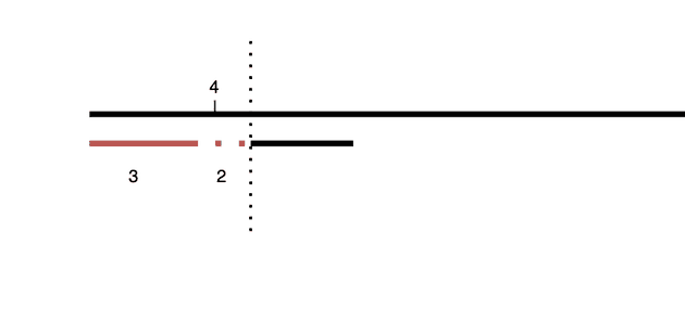
稍微解释下这个计算逻辑:
- 比如实线 3m,虚线 2m,长度 4m (累积直线距离)的点明显在虚线区域,做个取模 4%(3+2)=4
- 这个时候算出 4 大于实线长度,说明在虚线区域,就将这个地方的点设置为透明
- 同理如果是在 2 的区域,2 小于实线长度,说明在实线区域,就正常填色
增加lineDistance属性,参考代码如下:
// src/renderer/line.ts
// ...
// 新增一个needDistance参数,主要用于虚线和渐变线
createGeometry(data: ILine, needDistance: boolean = false) {
    const lineDistance: number[][] = [];
    points.forEach((point, i, list) => {
      // ...
      if (needDistance) {
        let d = 0;
        if (i > 0) {
          // 计算两点之间的直线距离
          d = getPointsDistance(
            [point[0], point[1]],
            [list[i - 1][0], list[i - 1][1]]
          );
        }
        distance += d;
        lineDistance.push([distance], [distance]);
      }
    });
    if (needDistance) {
      geometry.setAttribute(
        "lineDistance",
        new THREE.Float32BufferAttribute(lineDistance.flat(), 1)
      );
    }
}
接口变化如下:
export interface ILine {
  points: number[]; // 点集
  color: string;
  width: number;
  type: ELineType; // 默认是实线
  dashConfig?: {
    // 实线长度
    solidLength?: number;
    // 虚线长度
    dashLength?: number;
  };
}
编写虚线 shader 如下:
// 用于画单色虚线
export function getDashedLineShader(option: ILine) {
  const material = new THREE.ShaderMaterial({
    uniforms: {
      thickness: { value: option.width ?? 0.1 },
      opacity: { value: option.opacity ?? 1.0 },
      diffuse: { value: new THREE.Color(option.color) },
      // 虚线部分的长度
      dashLength: { value: option?.dashInfo?.dashLength ?? 1.0 },
      // 实线部分的长度
      solidLength: { value: option?.dashInfo?.solidLength ?? 2.0 },
    },
    vertexShader: `
      uniform float thickness;
      attribute float lineMiter;
      attribute vec2 lineNormal;
      attribute float lineDistance;
      varying float lineU;

      void main() {
        // 累积距离
        lineU = lineDistance;
        vec3 pointPos = position.xyz + vec3(lineNormal * thickness / 2.0 * lineMiter, 0.0);
        gl_Position = projectionMatrix * modelViewMatrix * vec4(pointPos, 1.0);
      }
    `,
    fragmentShader: `
      varying float lineU;
      uniform vec3 diffuse;
      uniform float opacity;
      uniform float dashLength;
      uniform float solidLength;

      void main() {
        // 取模
        float lineUMod = mod(lineU, dashLength + solidLength);
        // lineUMod>solidLength则返回0.0,说明在实线区域;否则返回1.0,说明在虚线区域
        float dash = 1.0 - step(solidLength, lineUMod);
        gl_FragColor = vec4(diffuse * vec3(dash), dash * opacity);
      }
    `,
  });
  material.transparent = true;
  material.side = THREE.BackSide;
  return material;
}
ok 胜利近在眼前,目前这个针对直线支持最好,曲线的话,得多一些点集数据才能确保曲线平滑过渡,否则可能要用到贝塞尔曲线平滑一下…(不过一般来说也不会让前端去做平滑吧至少我没碰到)
渐变线
其实有两种方式,一种是发出多个线段,每个线段带一种颜色,造成一种“假”的渐变效果,其实有时候也足够满足算法需求了,这种相对简单点;第二种是给一段线段,然后在起点和终点之间做线性渐变。这里看下第二种咋实现,主要差异也是在接口和 shader 里,需要做下颜色的线性插值,可以借助之前的 lineDistance 和线段总长度 lineAllDistance 的比例来插值。lineAllDistance 是新增的属性,暂时先给每个点都加上,或许有大佬有更好的办法也可以给点建议,这里就不贴代码了,可以参考源码 ~
接口变化如下:
export interface ILine {
  points: number[]; // 点集
  color: string; // 拿来做起点颜色吧
  width: number;
  type: ELineType; // 默认是实线
  endColor?: string; // 渐变色,作为终点颜色,color是起点颜色
}
编写 shader 如下:
// 渐变色
export function getGradientLineShader(option: any = {}) {
  const material = new THREE.ShaderMaterial({
    uniforms: {
      thickness: { value: option.width ?? 0.1 },
      opacity: { value: option.opacity ?? 1.0 },
      diffuse: { value: new THREE.Color(option.color) },
      endColor: { value: new THREE.Color(option.endColor) },
    },
    vertexShader: `
      uniform float thickness;
      attribute vec2 lineNormal;
      attribute float lineMiter;
      attribute float lineDistance;
      attribute float lineAllDistance;
      varying float lineU;
      varying float lineAll;

      void main() {
        lineU = lineDistance;
        lineAll = lineAllDistance;
        vec3 pointPos = position.xyz + vec3(lineNormal * thickness / 2.0 * lineMiter, 0.0);
        gl_Position = projectionMatrix * modelViewMatrix * vec4(pointPos, 1.0);
      }
    `,
    fragmentShader: `
      // 累积长度
      varying float lineU;
      varying float lineAll;
      uniform float opacity;
      uniform vec3 diffuse;
      uniform vec3 endColor;

      void main() {
        vec3 aColor = (1.0-lineU/lineAll)*(diffuse-endColor)+endColor;
        gl_FragColor =vec4(aColor, opacity);
      }
    `,
  });
  material.transparent = true;
  material.side = THREE.DoubleSide;
  return material;
}
数据自己 mock 的,想要线段更平滑就整多点数据吧 ~
